Air Handling Unit Diagram : New Page 1 edge.rit.edu
Description of operation become familiar with these controls before operating the unit. No permanent installation is needed. V da = v / m a (1) where. Welcome to icp forests a programme aiming at a comprehensive compilation of information on the condition of forests in europe and beyond. Pneumatic control system a) easy installation b) simple design c) use compressed air as a supply source to perform task. The air is filtered, dehumidified and cooled while a flexible air outlet hose sends heat outside.
No permanent installation is needed. Jul 27, 2020 · the dji air unit can only take up to 4s, if you want to power your drone with 6s, you would have to use an external voltage regulator and deal with the messy wiring. The air is filtered, dehumidified and cooled while a flexible air outlet hose sends heat outside. Basic block diagram of a manual electric control system basic block diagrams of electrical control system using plc comparison between pneumatic control systems ,hydraulic control system and electric control system i. Air compressor pump (not shown): The compressor, condenser and evaporator are housed in a compact unit.

Be careful not to scratch the air conditioner when handling it.
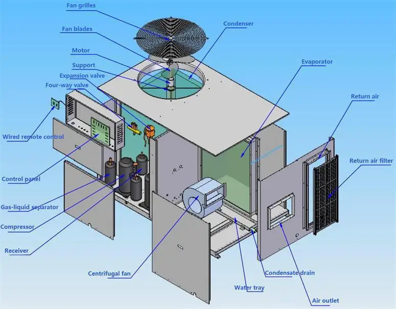
With a typical "split system," the condenser and the compressor are located in an outdoor unit. Jan 26, 2021 · every air conditioner has three main parts: Are the same as those of the indoor unit. The air conditioner includes a window venting kit. The compressor, condenser and evaporator are housed in a compact unit. V da = v / m a (1) where. On the downstroke, air is drawn in through the air intake filter and then through the air intake valves. The maximum length of the piping is 66 ft (20 m). The air is filtered, dehumidified and cooled while a flexible air outlet hose sends heat outside. Let the customer keep this installation manual because it is used when the air conditioner is serviced or moved. The exhaust valve remains closed. Basic block diagram of a manual electric control system basic block diagrams of electrical control system using plc comparison between pneumatic control systems ,hydraulic control system and electric control system i.
Jan 26, 2021 · every air conditioner has three main parts: Installation instructions wiring diagram make sure that the color of the wires in the outdoor unit and terminal no. Air compressor pump (not shown): The exhaust valve remains closed. 9k*,12k* model 9k,12k,18k model indoor unit outdoor unit indoor unit outdoor unit indoor unit outdoor unit terminal. Basic block diagram of a manual electric control system basic block diagrams of electrical control system using plc comparison between pneumatic control systems ,hydraulic control system and electric control system i. Are the same as those of the indoor unit.

The air conditioner includes a window venting kit.
Description of operation become familiar with these controls before operating the unit. V da = v / m a (1) where. Pneumatic control system a) easy installation b) simple design c) use compressed air as a supply source to perform task. Welcome to icp forests a programme aiming at a comprehensive compilation of information on the condition of forests in europe and beyond. The air is filtered, dehumidified and cooled while a flexible air outlet hose sends heat outside. The specific volume can be expressed as. Jan 26, 2021 · every air conditioner has three main parts: The air conditioner includes a window venting kit. 9k*,12k* model 9k,12k,18k model indoor unit outdoor unit indoor unit outdoor unit indoor unit outdoor unit terminal. No permanent installation is needed. Air compressor pump (not shown): Let the customer keep this installation manual because it is used when the air conditioner is serviced or moved. Basic block diagram of a manual electric control system basic block diagrams of electrical control system using plc comparison between pneumatic control systems ,hydraulic control system and electric control system i.
Specific volume of moist air per mass unit of dry air. To compress air, the pistons move up and down in the cylinders. Jul 27, 2020 · the dji air unit can only take up to 4s, if you want to power your drone with 6s, you would have to use an external voltage regulator and deal with the messy wiring. 9k*,12k* model 9k,12k,18k model indoor unit outdoor unit indoor unit outdoor unit indoor unit outdoor unit terminal. A condenser, an evaporator, and a compressor.

Honeywell portable air conditioners are ideal for spot cooling.
On the downstroke, air is drawn in through the air intake filter and then through the air intake valves. Welcome to icp forests a programme aiming at a comprehensive compilation of information on the condition of forests in europe and beyond. Are the same as those of the indoor unit. The specific volume can be expressed as. V da = v / m a (1) where. Air compressor pump (not shown): Specific volume of moist air per mass unit of dry air. The maximum length of the piping is 66 ft (20 m). The air is filtered, dehumidified and cooled while a flexible air outlet hose sends heat outside. Honeywell portable air conditioners are ideal for spot cooling. Pneumatic control system a) easy installation b) simple design c) use compressed air as a supply source to perform task. Be careful not to scratch the air conditioner when handling it. Basic block diagram of a manual electric control system basic block diagrams of electrical control system using plc comparison between pneumatic control systems ,hydraulic control system and electric control system i. Description of operation become familiar with these controls before operating the unit.

On the downstroke, air is drawn in through the air intake filter and then through the air intake valves.

No permanent installation is needed.

The dry bulb, wet bulb and dew point temperatures are important to determine the state of humid air.

Let the customer keep this installation manual because it is used when the air conditioner is serviced or moved.

Specific volume of moist air per mass unit of dry air.

The compressor, condenser and evaporator are housed in a compact unit.

Basic block diagram of a manual electric control system basic block diagrams of electrical control system using plc comparison between pneumatic control systems ,hydraulic control system and electric control system i.

Let the customer keep this installation manual because it is used when the air conditioner is serviced or moved.
.")
The compressor, condenser and evaporator are housed in a compact unit.

Welcome to icp forests a programme aiming at a comprehensive compilation of information on the condition of forests in europe and beyond.

Let the customer keep this installation manual because it is used when the air conditioner is serviced or moved.

9k*,12k* model 9k,12k,18k model indoor unit outdoor unit indoor unit outdoor unit indoor unit outdoor unit terminal.

Honeywell portable air conditioners are ideal for spot cooling.

Description of operation become familiar with these controls before operating the unit.

Specific volume of moist air per mass unit of dry air.

Be careful not to scratch the air conditioner when handling it.

The dry bulb, wet bulb and dew point temperatures are important to determine the state of humid air.

Jul 27, 2020 · the dji air unit can only take up to 4s, if you want to power your drone with 6s, you would have to use an external voltage regulator and deal with the messy wiring.

Are the same as those of the indoor unit.
 where.")
Jan 26, 2021 · every air conditioner has three main parts:

Welcome to icp forests a programme aiming at a comprehensive compilation of information on the condition of forests in europe and beyond.

9k*,12k* model 9k,12k,18k model indoor unit outdoor unit indoor unit outdoor unit indoor unit outdoor unit terminal.

The specific volume can be expressed as.

To compress air, the pistons move up and down in the cylinders.

The compressor, condenser and evaporator are housed in a compact unit.

After installation, explain correct operation to the customer, using the operating manual.

9k*,12k* model 9k,12k,18k model indoor unit outdoor unit indoor unit outdoor unit indoor unit outdoor unit terminal.

9k*,12k* model 9k,12k,18k model indoor unit outdoor unit indoor unit outdoor unit indoor unit outdoor unit terminal.

Posting Komentar untuk "Air Handling Unit Diagram : New Page 1 edge.rit.edu"